We explain seventeenth-century knowledge of these artistic and inherently computational structures in software, using a domain-specific programming language.
AmatiML is the name we've chosen for our domain specific markup language, designed to serve as an investigative tool to understand more about the history and evolution of instrument design, an inquiry we like to call “computational art history”. It's an extension of the Scheme programming language with programmable straightedge and compass constructions, and graphical procedures relevant to designing outlines.
Digital technology and software methods provide lucid, coherent tools for facilitating and enhancing the understanding inherent in this historical design tradition. tradition. They render that knowledge accessible, repeatable, and flexible, allowing rapid experimentation and communication. Algorithms encode methods, including those that are ubiquitious in lutherie. Programming languages don't exist simply to tell machines what to do. Well recognized as the engineering vernacular of software, they are more importantly the collective mother tongue of algorithmic ideas. Computational thinking is an accepted way of understanding complex, constructional processes; programming languages---a form of writing---provide a medium for us to express to each other what we know how to do.
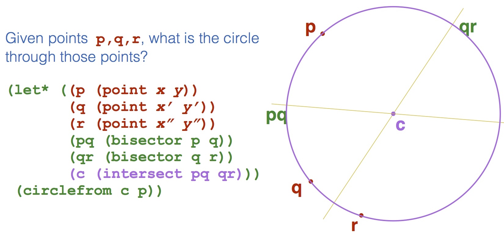
Here is a simple geometric problem: given points p,q,r in the plane that are not collinear, what is the unique circle where the points lie on the circumference of the circle? The "analytic geometry"way of solving this problem is to plug the three points into that equation, and you get three equations in three unknowns. Solve this set of equations, and you get the equation for the circle. The "Euclidean geometry""'' way of solving this problem is to draw, with a straightedge and compass, the line pq bisecting p and q, where every point on pq is equidistant from p and q; similarly, draw the bisecting line qr of points equidistant from q and r. (See the picture below.) Because p,q,r are not collinear (all on a straight line), the lines pq and qr intersect---at a point c equidistant from p,q,r. That's the center of the circle. The radius is the distance from c to p. There's no calculating---only drawing.
And that's what the code says, in so many words: let pq be the bisector of p and q, similarly qr the bisector of q and r. Let c be the intersection of lines pq and qr; the circle is one with center c, and radius distance from c to p. There's no numerical calculating by the user at the ``front end'', only geometric description---writing down what you would do with a straightedge and compass. When the code is run, the ``back end'' numerical calculations are done automagically by the geometry engine. This is not deep mathematics, by any means, but in hiding calculation, it lets Euclidean specification drive Cartesian computation. We call this ``geometric programming'', because you write down with code what you visualize doing with a straightedge and compass.
A suite of straightedge and compass constructions are what are used to design instrument forms based on geometric principles. An instrument outline is composed of an ensemble of circular arcs and straight edges, composed together in a precise arrangement.
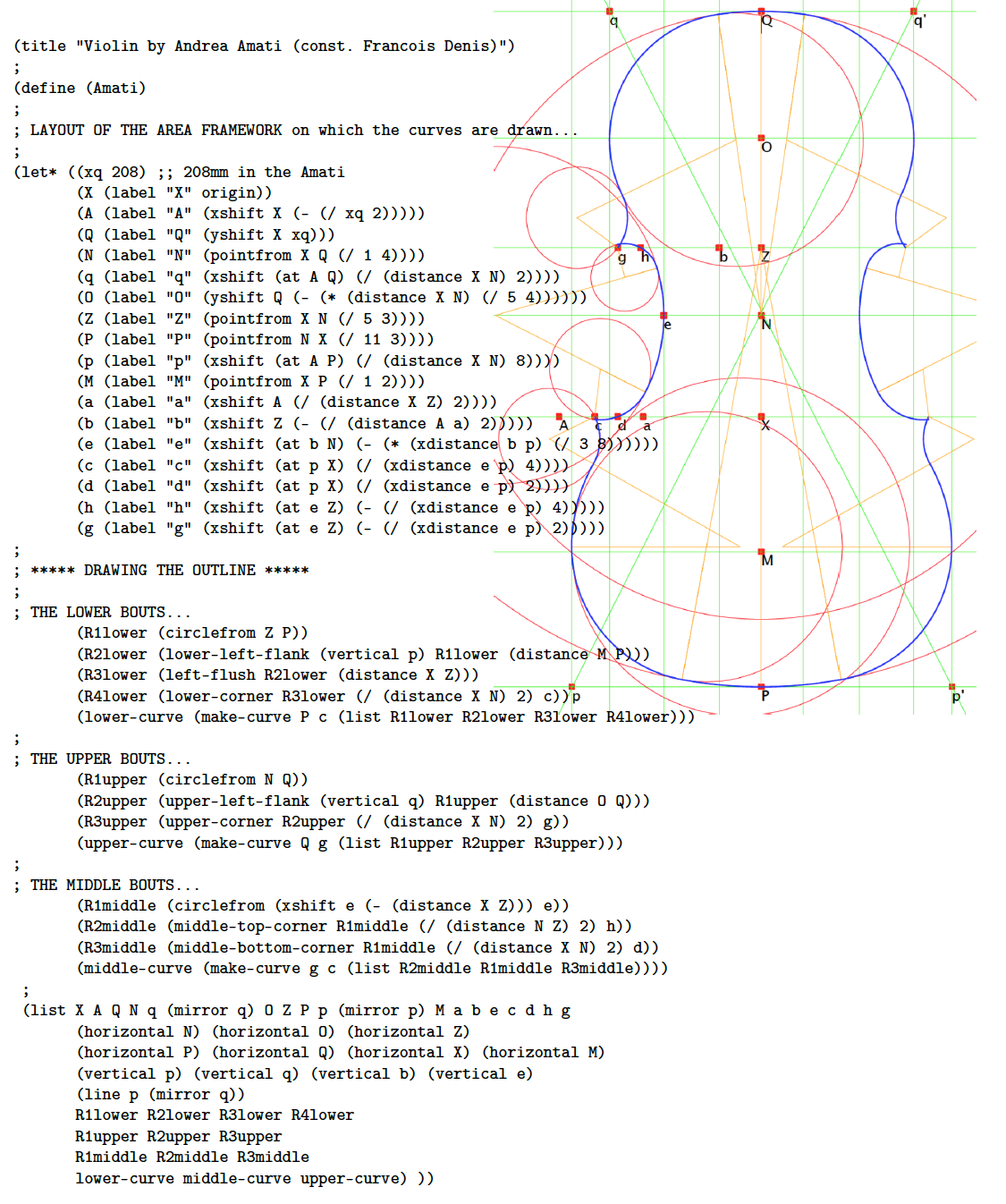
Here's an example: given the green line below (defining the width of the lower bout [third] of an instrument outline---see the instrument drawing in the lower right, below), and a blue circle defining the lowest curve of the outline, fit a red circle of a fixed radius r to be tangent to the green line and blue circle. The red circle defines the lower left flank of the instrument outline---see the drawing in the lower right of the figure below. The whole problem then reduces to the following: where is the center of the red circle located? The vertical yellow line defines where the center of the red circle has to be, if the red circle is tangent to the green line on the right: (vertical (xshift (point-on L) r)). Namely: take a point on the green line L, shift it over by the red radius r, and draw the vertical line through that shifted point. The yellow circle defines where the center of the red circle has to be, if the red circle is tangent to the interior of the blue circle: (circle (center C) (- R r)). Namely: the circle with the same center as the blue one, only with a radius of R-r. Now, intersect the yellow line and the yellow circle: the intersections are marked below by two red dots. The lower, bottom one is the solution---the center of the red circle.Here is the first of seven canonical models described in Francois Denis's book (Traite de Lutherie: The Violin and the Art of Measurement, pp. 114--129), a violin by Andrea Amati. The geometry engine outputs full-scale PDF of the instrument outline. This drawing can be modified and elaborated in various ways. The additional arcs and lines elaborate the straightedge and compass constructions that are used to assemble, as an ensemble, the instrument outline.

Internal forms for the Stradivari Cristiani violoncello, made for a reduced-size instrument that is 740mm long, with bout widths commensurate with a classic Stradivari forma B instrument. The first was made from a full-size drawing, and cut out on a band saw. The second (made in a lot of 40 at the Oberlin Violin Workshop in summer 2015) was made using the PDF of the drawing to drive a CNC router.
Here is an internal form made direct from PDF for the drawing: